DK3QN's Ham Radio Menue
Home CW QRP rigs QRO rigs Boatanchors Antennas Amplifiers EME SDRs Miscellaneous Impressum email
FT-450AT foot bar considerations and mounting hints
Background:
Quite a number of users have been complaining in the net about the FT-450's small tuning knob and the incoveniance
in tuning frequencies that comes with it. The effect of felt inconveniance is even more stressed by the fact that the
FT-450 does not come with any means of lifting the front up a bit e.g. by height-adjustable feet or a flippable foot bar.
After I had got my FT-450AT mid August 2009 and after having used it for a couple of hours, I came to the same
conclusion as many others: tuning frequency with the small tuning knob gets more awkward the longer you
"play" with the radio.
I tried to analyze this "issue" and finally came-up with 2 possible root causes:
#1: tuning knob is too small to be used ergonomically,
#2: angle of front panel is the "problem", as knob cannot be turned ergonomically in this position (front panel
too steep / unit position too flat).
In the following, I will describe my findings re. #2, as I was convinced from the beginning that this was the real
main "issue".
With #1, you cannot do much about it anyway.
Web research for a solution and placing the order:
After some web research I finally found some hints in the FT-450 yahoo group. Someone there mentioned that he
had installed a foot bar which he ordered as a spare part for a Yaesu FT-847. There was also a hint that FT-450
foot bars are available from martin lynch & sons ("ML&S") in the UK.
Owning an FT-847 myself (foot bar as a standard feature) and looking at both units (847 and 450) at the same time,
it was quite obvious to me, that an FT-847 foot bar should be compatible with the 450 front mounting holes' position.
However, before ordering a spare 847 foot bar at my favourite ham radio dealer in Germany, I went to the martin
lynch & sons ("ML&S") web site and searched for the FT-450 foot bar,
 I finally found the item, ordered it via their web shop ("Stand for FT-450")
and payed the bill by PayPal.
Total cost including registered shipping to Germany was UK Pounds 22.53.
I ordered/payed on a late Thursday, the package with the foot bar arrived
at my door the following Monday morning!
That's pretty fast, isn't it! Hats off to martin lynch & sons!
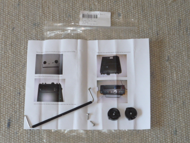
(picture above) The package content: 2 plastic feet, 2 self-tapping screws,
foot bar and mounting instructions.
The ML&S "Stand for FT-450" (isn't that an FT-847 stand?):
 The "Stand for FT-450" proved to be quite the same as the
FT-847 foot bar as you can see in the picture. This shows
the bottom of my FT-847 with the standard foot bar mounted
towards the front of the unit.
For camparison, I just laid the "FT-450 stand" (2 feet,
1 bar and 2 mounting screws) onto the bottom cover in
the midth of the bottom cover.
The 2 plastic feet and the bar are exactly the same as the
FT-847 fitted foot bar with the exception of the screws!
More on that further down this page.
So, if you wish to raise the front of your FT-450 up for better
access to the tuning knob: FT-847 foot bar will do.
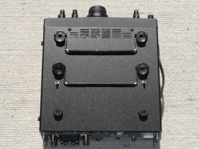
picture above: FT-847 bottom view with "Stand for FT-450" laid in center
Mounting hardware of the "Stand for FT-450":
The stand as ordered from martin lynch & sons comes with 2 self-tapping screws. The "little" issue here
is that the size of these screws is such that by installing them you will definitely widen the original diameter
of the 2 front foot-mounting holes of your FT-450 significantly from their original diameter to a somewhat larger
diameter.
In case you want to switch back to the original FT-450 feet, which are simply fitted by a through-hole clip,
they will not be able to make a tight fit anymore. You may then need to glue them in.
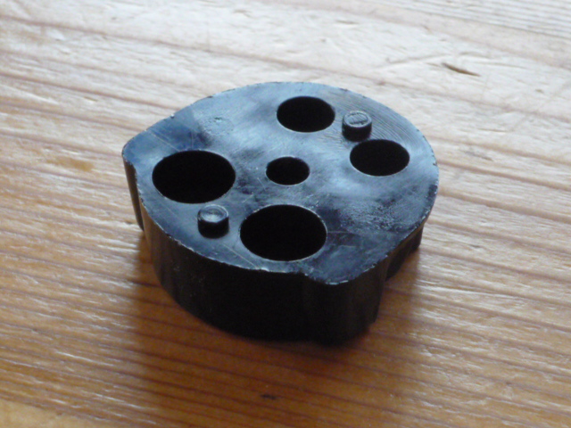 Before you can mount the 2 feet which hold the stand to the FT-450 bottom
cover you need to get rid of the 2 plastic pins that protrude from each plastic foot.
They need to be cut-off flat or sanded away so that the result is a flat surface across
the top of each foot.
With the FT-847 these 2 pins have a certain function. These pins have 2 corresponding
little openings in the bottom cover of the FT-847 where they fit through when
mounting the foot stand to an FT-847. This keeps the feet firm in place avoiding any
turning round of the feet especially during the mounting process.
With the FT-450 there aren't any of such openings in the bottom cover! Thus, in order to have the 2 feet
mounted flat onto the FT-450 bottom cover, you need to cut or sand these pins off. This is not mentioned in the
ML&S installation sheet.
Finally, as far as the screws are concerned, I decided to take another approach than the ML&S provided hardware,
as I did not want to have the diameter of the foot holes changed but let them rather be in the original size.
My way of screw-mounting the foot stand:
I searched for some stainless steel screws and washers / spring washers and ended up with the following
solution:
 2 stainless steel threaded screws, size M3 by 20mm, 2 washers M3, 2 spring washers M3,
2 nuts M3.
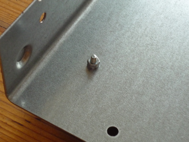
The M3 threaded screws easily fit through the bottom cover foot holes without doing any
harm to the holes. Position the feet and bar correctly and tight-mount the screws/nuts.
This picture below is a bottom view of the FT-450AT interior (bottom cover removed).
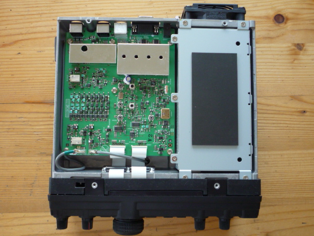
See the internal tuner inside the FT-450AT?
It's the large box at the right hand side of the unit (see picture at left).
See the 2 holes on the right hand side of the tuner box, one towards the rear
and one towards the front?
These 2 holes are exactly at the position where the left-hand side (remember:
this picture shows the FT-450AT upside down!) bottom cover foot fixing holes
are located. Any limited (!) excess screw length by the foot fixing screw can "dive" into those openings without
putting pressure onto the tuner box!
WARNING!
Whatever method of screw-mounting the stand/foot you may adapt: take care that any excess screw length
does fit through these holes in the tuner box without touching the tuner box (avoid mechanical stress)!
Make sure that any excess screw length is kept to an absolute minimum (very few mm) in order to avoid
any contact / short circuit with the antenna tuner's internal electronics!
I do not take any liability for any damage caused by disregarding my warnings!
The holes in the tuner box are not big enough to take an M3 nut. So make sure that there is enough space
between the tuner box and the foot mounting nut inside the bottom cover. If necessary leave out the washer
at the nut side to get more clearance between nut and tuner box. Any mechanical stress to the tuner box
must be avoided!
Results:
From an esthetic point of view I am very pleased with the result. My FT-450AT now got a "professional"
looking foot stand which can be flipped-in and -out!
However, from an ergonomical point of view I am not a 100% pleased with the result.
Here is the reason why:
Remember: we have installed an FT-847-designed foot bar to the FT-450.
Look at this picture (bottom view):
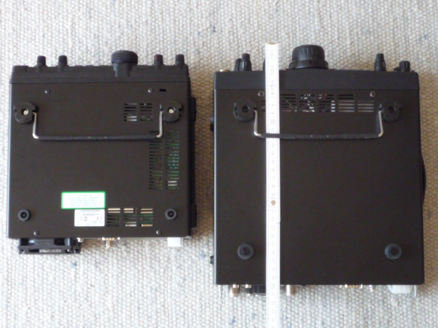 Left hand side is the FT-450, right hand side the FT-847.
Both units are positioned such that the foot bar of each unit is about
in line with the other.
What you will notice is that the foot bar's distance from the front of
each unit is about equal.
On the other hand, the distance from the foot bar to the rear of the
unit, the rear pair of feet, is much shorter on the FT-450AT (left).
What does that mean now for my FT-450?
Well, this means that the rising angle caused by the shorter distance between front to rear feet is
much steeper at the FT-450 with exactly the same foot bar installed on both transceivers.
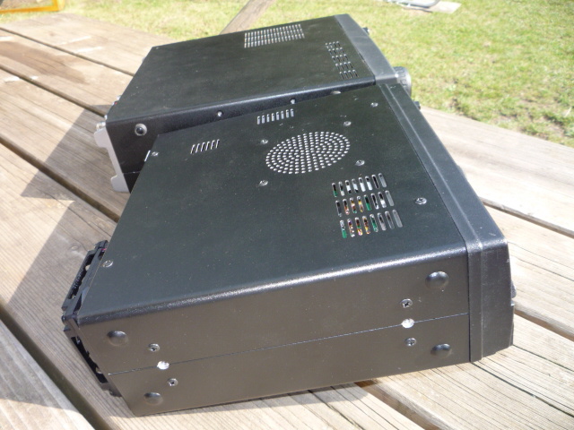
You can see that more clearly when looking at both units from a side view.
See here (picture below, in the front: FT-450AT, in the back: FT-847):
 You will easily notice 2 things:
#1: the front panel of each unit is at about the same height,
#2: the rear of the FT-450AT "drops off" more rapidly.
This difference in angle is caused by the shorter housing of
the FT-450AT.
As a net result, for the FT-450 the front panel with the "VFO"
knob gets elevated quite significantly more than the FT-847.
Turning this into numbers:
With the bar stand originated from the FT-847, the bottom edge of the front panel of the FT-450 gets
lifted up to approximately 5.5 cm! This is a change from the standard feet bottom edge position by
about plus 4.5 cm! This is quite a lot and may be a bit too much for some people!
As the operating position for the VFO knob now went a bit more into the horizontal plane, turning the
knob now - for some people - just may be a bit too "flat". I'd assume this to be especially true for
people with smaller sized hands as they may now need to raise their hands up a bit too much in order
to be able to spin the VFO knob freely and effortlessly. YMMV.
Alternative low-cost implementation for lifting the front panel:
I went to the local hardware store and bought 2 pieces of what I call "rubber door stoppers".
Their dimension is 2.5 cm high and 3 cm of diameter. They didn't have slimmer ones.
You need significantly longer M3 screws for the mounting. Please read my "WARNINGS" above for the
correct mounting hardware. Else, you may damage your FT-450 transceiver!
These stoppers allowed me to lift the bottom of the front panel to about 3.5 cm up.
For the size of my hands that turned out to be an ergonomically perfect position.
As a draw-back, these stopper are "always there". You cannot quickly remove them for easy transport
or packing of the transceiver.
For the time being I stayed with the flippable foot bar and hope to get along with it. In any case, this
provides a much better operating position for the transceiver than having the FT-450 standing "flat"
on your operating table.
Finally: another "hidden danger" when lifting the front by means of higher front feet
There is another danger which can impact your FT-450 severely, in case you do any front feet modifications.
You should always be aware of this!
This danger stems from the fact that most of the FT-450 back panel connections are located at the very
low rear side of the transceiver.
Look at this picture:
 As you lift the transceiver front by some after-market foot extensions,
the transceiver's rear edge gets more tilted downwards to the table
surface.
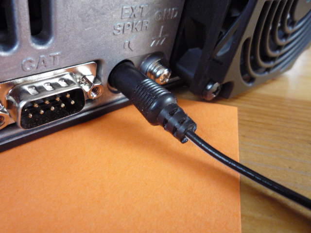
This picture shows the FT-450 rear with the FT-847 foot bar installed.
You can see a 3.5mm loudspeaker plug attached to the transceiver.
Please notice that the 3.5mm loudspeaker plug end is only some
3mm above the table surface!
To the left you can see the RS-232 connector. Left to that (not shown
in the picture) are the mini DIN connectors.
In the picture I have slided an orange small piece of paper under the rear edge of the transceiver in order
to demonstrate that there is still some clearance between the rear bottom of the transceiver housing and
the table surface. But the gap there is very small!
Now, why is this "dangerous"?
You (if you own an FT-450) and I know that the FT-450 internal speaker doesn't sound to good.
As far as I am concerned I plug in an external speaker into the back panel speaker jack whenever possible
(see picture).
I'm running my FT-450 mainly in CW, occasionally SSB. No digital modes, no amplifier connected. So, the
speaker connector so far for me was the only "watch-out" factor.
But the possible issue applies in general for almost all rear-panel connections.
For those people running digital modes or an amplifier, this issue may even be more essential in avoiding
damage to their rigs.
Imagine what happens if you have the rear connectors of your FT-450 well-staffed with according plugs.
And then, for whatever reason, you lift the front of your transceiver.
What happens then is, that your rear connected plugs will "hit" the table surface and induce an increasing force
to most of the connectors at the transceivers rear, especially those ones that are "only" fixed by on-board
solder joints, like the speaker connector. A potential source of trouble with the rear connectors.
You should be quite aware of this situation and always take this into account!
As far as myself is concerned: I will change my loudspeaker plug to a 90 degrees plug (to make the plug end
much shorter compared to a 180 degree, i.e. flat-out plug) where I will make sure that any time I insert this plug,
the cable end will show "north" (i.e. exiting to the top).
Other topic: built-in fan, possible substitute
A quick look at my FT-450 integrated fan manufacturer data, printed on the fan rating label, and a following
web search gave the following results (not certified):
Manufacturer: KAIMEI ELECTRONIC CORP.
Model: KF0715S1L-R
Rotary DC fan brushless
Sleeve bearing
12 V DC at 0.14 A
My (not certified) web search data didn't give returns with exactly the same model number.
What I got back as a nearest product, was for a product of this company showing the best match (not same)
missing parameters:
Air flow: 24 cfm
Static pressure (inch, H2O): 0.093
Speed: 3000 rpm
Noise: 28 dbA
Again: I'm not sure about the correctness of this data. Please double-check yourself!
And here's the disclaimer:
Please be aware of, that if you do any changes to the transceiver which are not approved by the manufacturer,
you are voiding your warranty!
to be continued...