DK3QN's Ham Radio Menu
Home CW QRP rigs QRO rigs Boatanchors Antennas Amplifiers EME SDRs Miscellaneous Impressum email
Boat Anchors
"Boat Anchors" designates ham radio equipment that was developed and being sold a long, long time ago.
In general, this means in the last century. In a "narrow" interpretation it means around WW2 and earlier,
or in the 50's.
I use this term for any of my "old-fashioned" ham radio equipment which is about more than 25 years old.
Re-visiting a Ten-Tec Corsair II: have we learned from the past? (02-Nov-2010)
Recently I aquired another second (or third hand) Corsair II from an estate.
The radio - fortunately - turned out to be in rather good shape electrically as well as mechanically.
It came with the separate VFO, PSU and an antenna tuner which was "customized" a lot by one of
the previous owners.
My other two Corsair II sets are such as one is a "parts only" set and the other one still needs some
work at some of the PCBs.
So, the new entry just fitted pretty well to the other Corsair II sets.
General comments:
There is so much "talk" recently about "roofing filters" with contemporary transceivers.
Rarely anybody tells you that this is an "ancient" approach already. It has been a "standard" with a
number of transceivers decades ago!
Some of my ham radio "godfather" elmers already told me in the 70's of last century:
"A good ham band receiver has to have it's final selectivity as close to the "front end" (first mixer, i.e.)
as possible in order to "free-up" subsequent stages from close-in strong signals."
Aha!
Now, in 2010, the "big name" manufacturers do recall this elementary wisdom again ;-)
Applause, applause ;-)
There have been some mods for more modern-style transceivers in the past years. The main focus
was to get the first IF bandwidth as narrow as possible, depending on the implementation of the first
IF frequency.
With up-conversion rigs first IF most likely was in the range of 70 MHz. At this frequency, narrow bandwidth
filters are very difficult to implement. As a consequence, the narrowest filters (after market) were around
3 to 5 KHz. Bob Sherwood offered and still offers such "after market" "roofing filters" for some of the more
recent rigs. The original first IF filters in these transceivers was in the 10 to 15 KHz bandwidth range.
The reason these rigs are in a need for the roofing filters are sort of a "blame" vs. rig developers.
Please read on wide open first IF strong signal issues, passing the first mixer and also hitting the second
mixer in this sort of radios somewhere else in the web in detail.
In short: the problem with a wide-open front end is such, that all signals in the - say - 15 KHz first IF filter
bandwidth are hitting the second mixer stage as well. If the signals within this pass-band are strong enough
they will cause mixer stages to be driven to their limits. The inheritant problem then is related to "blocking"
which basically means that weak stations on frequency vanish as they are "blocked out" by some strong
stations within (e.g.) the first IF filter bandwidth (e.g. 15 KHz). The nasty thing with this is that you don't
hear those strong stations as they are outside of your final bandwidth. But they are there and do affect
the RX system. Or, even more likely, strong stations inside the 1st IF pass-band generate 3rd order IMD
products, kind of "gost signals", which can wipe out weaker signals in the pass band.
Pretty elementary stuff, one might comment.
However, most of the ham radio transceiver designs of the last decade (and more) up to now used this
sort of "broad bandwidth" IF up-conversion technology.
One of the early companies reflecting the "old elmer" recommendation and also implementing this
"ancient" technology into a mass market product was Elecraft with their K2 Transceiver.
What they basically did was going away from the "modern" up-conversion and multi-IF mixing scheme
back to a year 1970 standard: SINGLE IF, with switchable bandwidth filters at this first IF!
Ten-Tec, with the Orion I and follow-up radios came the same way.
What does this all mean with respect to a Ten-Tec Corsair II?
Looking at a Corsair II as of today, one can make the following statements:
> The rig was shipped in the 80s of last century. It's design time may have been in the late 70s,
early 80s.
> It uses 2 IF's in order to implement a pass band shift feature. First IF at 9 MHz, second at 6.3 MHz.
> First IF at 9 MHz is at ca. 2.5 KHz bandwidth. Narrower bandwidths are implemented by plugging-in
narrower bandwidth IF filters at the second 6.3 MHz IF.
> By "modern" standards it's got a standard 2.5 KHz "roofing filter" at the 9 MHz first IF (could also be
implemented a lot narrower and possibly can be, depending on mode of operation).
> Pretty low-noise pre-mixed L/C-VFO wih little phase noise.
> Dual watch within the same ham band when using the external second VFO in addition to the transceiver
VFO.
Draw-backs:
> Frequency accuracy: counter only has 100 Hz resolution, calibration varies band by band.
> Frequency stability: due to thermal impact frequency stabilizes after 30+ minutes.
> The CW side tone audio quality "sucks": it's not a sine wave audio but a rather annoying sawtooth
kind of audio response (there is a mod for that in the web).
Conclusion:
Despite the other "modern" TRX technologies (DDS, DSP), the "old ancient" Ten-Tec Corsair II is still a
very "modern" rig by many means as explained above. It looks like it's got no issues with what many
"modern" HF transceivers share in common: it's dynamic range seems to be not noise limited due to
a somewhat "noisy" PLL/DDS VFO!
Further Readings:
W7KF has a nice web page on the Corsair-II. I share all of his comments on this particular radio.
See his Corsair-II web page here:
Link to W7KF Corsair-II web page
Important safety notice: (update 22-Jan-2010)
A word of "Warning", especially if you have not grown-up in the "tubes" type era:
"Boatanchors" almost always sport some sort of tube(s) in it. A "tube" is a totally different animal compared
to a semiconductor in the context of "Danger" to your life. Yes, I do mean "your life".
This is because the voltages in use for supplying a tube set are in the hundreds and up to a thousand voltage
level whereas in semiconductor sets you'll typically see something like a max. 12 to 50 volts DC supply (if the
low DC voltage is fed by an external PSU).
If you are going to open up such a box and do repairs and/or alignment, you *have to be* very careful with
what you are doing and *must* understand what and where you are doing things.
This, e.g., includes the appropriate measuring equipment tools for your particular task.
Give you an example:
You *cannot* take a standard voltmeter, spec'd at maybe 300 volts, to check your boatanchors finals plate voltage,
which is, most likely, in the 800 to 900 volts range, in the case of a transmitter/transceiver. In case of a
high power tube amp, voltages may be up to 3000 or 4000 volts!
If you don't absolutely care about these issues, you'll be most likely be "dead" during your "exercise". This level
of voltage will kill you right away.
This *Warning* also applies to any probes of your test equipment. These probes *must* cope with the voltages
which they are supposed to be going to be measured, DC and AC!
Just make sure that you are doing things *right* and absoletly *consciously* when dealing with voltages any higher
than - say - 40 volts.
In my youth, when trying to repair a tube radio, I got a stroke by the 220 volts main supply primary. I've survived,
but I've sweared *never ever* to go that risk! And I am acting accordingly!
The purpose of my comments is not to keep you off and away from putting hands-on/repairing of "Boatanchors".
But you certainly need to take very special care in any respect when dealing with such devices for your own sake
and health.
Please be always aware of this!
The History
Most of the "old stuff" is equipped with electron tubes only. There may be some semiconductors in these
rigs, but there they mainly act as power rectifiers or low power AM demods or AGC rectifier diodes. In any
case nothing really serious to speak of as long as SSB/CW reception is concerned.
This is particularily true for any kind of ham radio equipment that came to the market about until end of the
60's.
 Mid to end of the 60's, some of the ham radio equipment started to sport a
few transistors in their VFO circuits, mainly because of thermal stability
improvements. The "stuff" didn't simply get that "hot" next to VFO components
like coils and capacitors, compared to tubes.
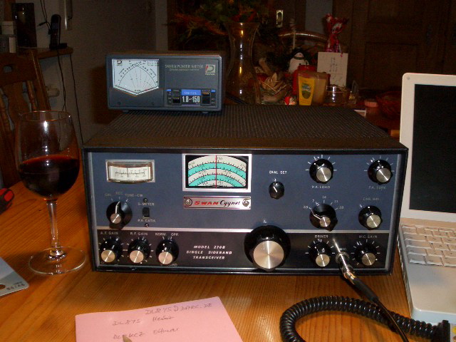
Picture at left:
Swan Cygnet 270B from the 60's, a glass of red wine and an old Apple iBook G4
in service on 80m SSB
The 70's brought a tremendous change in so far that a lot of ham radio equipment was converted to semiconductor
technology. In general, the conversion was focussed around receiver building blocks plus low power transmitter
stages. Medium to high power semiconductor transmitting devices were not yet available at that time at reasonable
cost. So, typically driver and TX final stages still remained to be tube-type technology. The typical configuration in
those days were around a 12BY7 tube as a driver and a pair of 6146's as the finals, a very rugged set-up.
The conversion to semicondutors instead of tubes caused a real draw-back in receiver performance at that time.
Reason was that the large-signal capabilities of the semiconductor components was far below the tube-type
circuits. Remember: we are talking about the early 70's. At that time semiconductors were still based on Germanium
or early Silicon type of technology!
The conversion was mainly driven by the Japanese brand Yaesu, aka "Sommerkamp" in Europe (import company
for Europe). Yaesu's most famous rig during that time was the FT-101 line of HF transceivers (up to the "F" model).
The FT-101 (plus "B", "E" and the late rare "F" model) was already fully transistorized with the exception of the driver
and final TX stages, a pair of 6JS6 tubes in this case.
If you are particularily interested in the 101's. have a look at NW2M's excellent website covering almost everything
you may need to know about the 101 generation. See here.
The receiver section was very "hot" (very sensitive), however, the dynamic range was very limited by today's figures.
This was why the "Attenuator" switch came into life. Reason was to move the (limited) dynamic range window into
an area where the receiver was getting less over-loaded by strong signals. This feature is still around in contemporary
transceivers these days (2009). Wonder why?
The 80's brought another break-through in ham rig technology: receivers were getting much better due to improved
semiconductor large signal capability (push-pull MosFET mixers and diode ring mixers) and the driver and final TX
stages being converted to semiconductor devices. An example for this is the Yaesu FT-107 series of transceivers.
In the US, Ten-Tec was one of the famous companies who had identified that change and who came out with a
number of fully transitorized rigs quite early. I still own quite a few of their early semiconductor rigs and - hats off -
they still work quite nicely under today's propagations! Still very usable, despite the "old" technology!
Introduction of "PLL"
Another change happening in the mid to late 80's was the introduction of "PLL" for VFO circuits. Before that, VFO's
were either running on a "direct" frequency. With that I mean that the VFO frequency was such that the VFO frequency
was changed per band to achieve the IF. Many of the "SWAN" radios used this kind of technology and the result
RX-wise was pretty good (single conversion). However, frequency stability on the higher amateur bands was
compromised due to the high-frequency free-running oscillators and related frequency drift issues at higher frequencies.
Another method was pre-mixing a VFO signal with a crystal oscillator sporting the set-band crystals for the amateur
bands and injecting the resulting signal into the mixer. "Drake" did that very much e.g. with their "TR4" series of
transceivers with good results.
A third method was e.g., to do the conversion stretched over 2 mixers, where one of the mixers got the XO (Xtal
Oscillator injection / band setting injection) and the other one the VFO injection in order to tune the band. Typical
example of this technology is a Collins KWM-2.
Getting back to the starting point here: PLL controlled VFO's
That really brought a new experience to the topic of "frequency stability". You could now really rely on your "VFO"
frequency readout and be quite sure that your TX signal is not drifting in frequency!
On the other hand: early PLL circuits suffered from severe "phase noise" which deteriorated the RX signal under
certain propagations (please "google" in the web re. this topic, if you are interested).
However, there are some really well-performing PLL rigs out there from the "old days" which are still usable these
days, like the Icom 735, 730 or 740, just to name a few.
My collection of boat anchors:
Collins 75A-4; 75S-1, -S2, -S3; 32S-1, -S3; KWM-2, -2A; 30L-1; R390A/URR;
If you are interested in Collins radios I would recommend visiting the "Collins Collectors Association" website here.
Lots of very useful information on Collins equipment.
It must be said that most of the "old" Collins equipment is being offered (and mostly also sold) at quite high a prize.
I may add that from my perspective this in not quite justified by the quality or performance of those radios.
Prizing is purely driven by many Collins collectors and their desire to own one or many of the famous Collins
radios.
High prizes are asked (and paid) especially for 32S-3A (TX) and 75S-3C (RX) units (1k US $ and more per unit).
This is due to the fact that this was the last generation of Collins tube receivers and transmitters. Aditionally,
they are much seeked after because of their extended frequency coverage capability, as the internal X-tal oscillator
crystals can be switched by a front panel switch to a second level set of X-tals allowing for an additional frequency
coverage, e.g. allowing operation on some of the WARC bands, if the appropriate crystals are inserted into the
crystal holders.
75S-1, S-2 and S-3(B) receivers and 32S-1, S-3 transmitters didn't have this capability built-in.
The same difference applies to KWM-2 and KWM-2A transceivers where the latter also had this crystal selection
switch built-in. I need to mention that many of the 2A transceivers, due to their frequency coverage capability, had
been used in commercial service (military, etc.) and sometimes not been treated carefully. So, better watch out and
double-check the unit's condition before buying.
BTW: Collins offered a complete package of crystals which would cover all possible frequencies for a Collins radio.
This option is called the "CP-1" crystal package. It's a small plastic bag with little plastic chambers where all the
extra crystals are sitting. In the bag the chambers for the "standard" ham radio crystals are not populated as those
crystals were already populated in the radio itself. So, if you are looking at a CP-1 pack, it's normal that those crystals
are missing in their appropriate chambers. Make sure that all others are there in their chambers!
These CP-1 bags can still be found from time to time e.g. on eBay US. Prices for a complete CP-1 bag are around
100 to 200 US $.
If this all does not keep you away from trying some of the tube era of Collins ham radio stuff: I'd recommend looking
for set of 75S-3(B) receiver and 32S-3 transmitter. They are not so much seeked after by collectors, are offerd more often
than the latest edition of this kind of radios, and thus prizes are more reasonable as you don't generally see this
"I pay no matter what you ask for it" attitude.
Drake 2B & 2BQ; 4-B-Line; 4-C-Line; the 2B and the 4-B-Line had a high-grade copper sheet chassis, where the later
4-C-Line was built around an "ordinary" metal sheet chassis;
Galaxy V (various) and GT-550 (various), lots of watts in a small package
Hallicrafters SR-150; one of the very few transceivers from US-based manufacturers which at that time already had
a built-in RIT (Receiver Incremental Tuning, aka "Clarifier");
Hallicrafters SX-101 (RX) and HT-32B (TX)
Hallicrafters "Loudenboomer" HF amplifier, using one Eimac 3-400Z tube
Kenwood TS-520SE, TS-900 (basically a "high-quality" implementation of a TS-520)
National NCX-5; NCX-3; NCX-200;
Swan 270 Cygnet 270B and a 300B with 16 pole crystal filter; single conversion rigs, where the VFO was switched per band
in order to match the fixed IF at around 5.5 MHz;
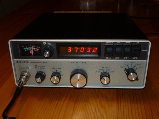 Swan/Cubic Astro 150A (various), a quite unique rig, fully transistorized, sporting a PLL VFO;
very robust;
There was a special version made for governmental use which covered 2 to 12 MHz.
This version was called "Astro D".
I was lucky enough to get hold of one Astro D. It came as a package where transceiver,
PSU and antenna tuner were integrated into a small attache case.
Picture at left:
Cubic Astro 150A on 80m SSB
Ten-Tec Omni D, Triton-4, Delta-580, Corsair-2
Yaesu FT-101E (various), F; FT-107; FT-7B
... to be continued